Formula SAE Wheel Speed Sensors
Custom magnetic position & velocity sensors for wheel speed measurement on WPI’s Formula Hybrid+Electric vehicle.
One of the major projects that I worked on for WPI’s formula SAE team this season was improving and finishing the implementation of a magnetic wheel speed sensing system that didn’t get finished the year before.
Concept
The general idea of the wheel speed sensing system is to use linear hall sensors on a PCB mounted next to a multipole magnet ring attached to an axle/driveshaft with alternating N/S poles, the hall sensors spaced to be 90 electrical degrees apart. With a properly designed magnet ring, the radial component of the magnetic field produced is approximately sinusoidal and thus the signal from the hall effect sensors can be thought of as two-phase sin/cos quantities allowing for determination of the instantaneous (electrical) position of the magnet ring. Through some digital filtering, this can be used to obtain axle velocity for telemetry and traction control.
The previous setup consisted of a board with a SPI ADC on it that would interface with another “IO board” on the car’s CAN bus for signal processing. Unfortunately the ADC used on the board wasn’t viable for properly digitizing data from the onboard hall sensors at a fast enough speed to get useful speed information, so I was tasked with re-architecting and reimplementing the system to be functional and hopefully improve some other important characteristics such as noise and bandwidth.
Design
Aside from the issues with the SPI ADC on the previous system, early in the year I discovered some more limitations of the previous setup when I bypassed the ADC and started implementing the signal processing on another board with an integrated ADC.
- The existing magnet rings produced highly distorted waveforms making it difficult to get accurate velocity information
- Lack of a stable (crystal/MEMS) oscillator on the board doing signal processing limits the accuracy of velocity measurements
- The noise from just two hall effect sensors operating in a very noisy environment (right next to a 80-some kW high voltage tractive system) limits either the precision of velocity measurement or reduces the effective sensor bandwidth after filtering has been applied
The new architecture that was decided on aimed to mitigate these issues and produce a sensor compatible with other architectural changes planned for next year’s telemetry/DAQ system.
- Four hall effect sensors: having four sensing elements doubles the amount of data being processed to reduce noise, add redundancy, and allow for better compatibility with various sized magnet rings (with differing pole pitches) while not adding much cost to the overall system
- RS485 Interface: Streaming data from the sensor board (ADC) to the signal processor with a proper differential serial interface is much more robust to noise than SPI or analog
- MCU with integrated ADC: A STM32G0 on the sensor board has more than enough ADC resolution/bandwidth and can do some initial filtering and formatting of data before sending it out over the RS485 interface
- ADC pre-drivers: adding buffering to the hall sensors allows running the ADC at full speed (no longer limited by the source impedance/sample caps) - not neccessary for bandwidth, but helpful for oversampling!
Sending raw data over the RS485 interface removes the need for a stable oscillator on each sensor board since the board doing signal processing can timestamp data from two sensor boards with it’s crystal oscillator and compensate for drift/measurement jitter.
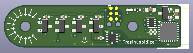
Wheelspeed board design
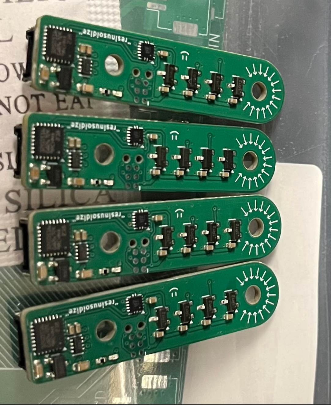
Four assembled sensor boards
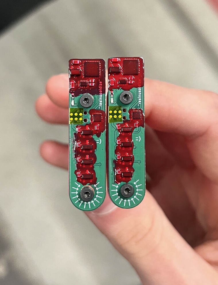
“Conformal Coated” (nail polish) and taped wheelspeed boards ready for mounting by the car’s rear driveshafts
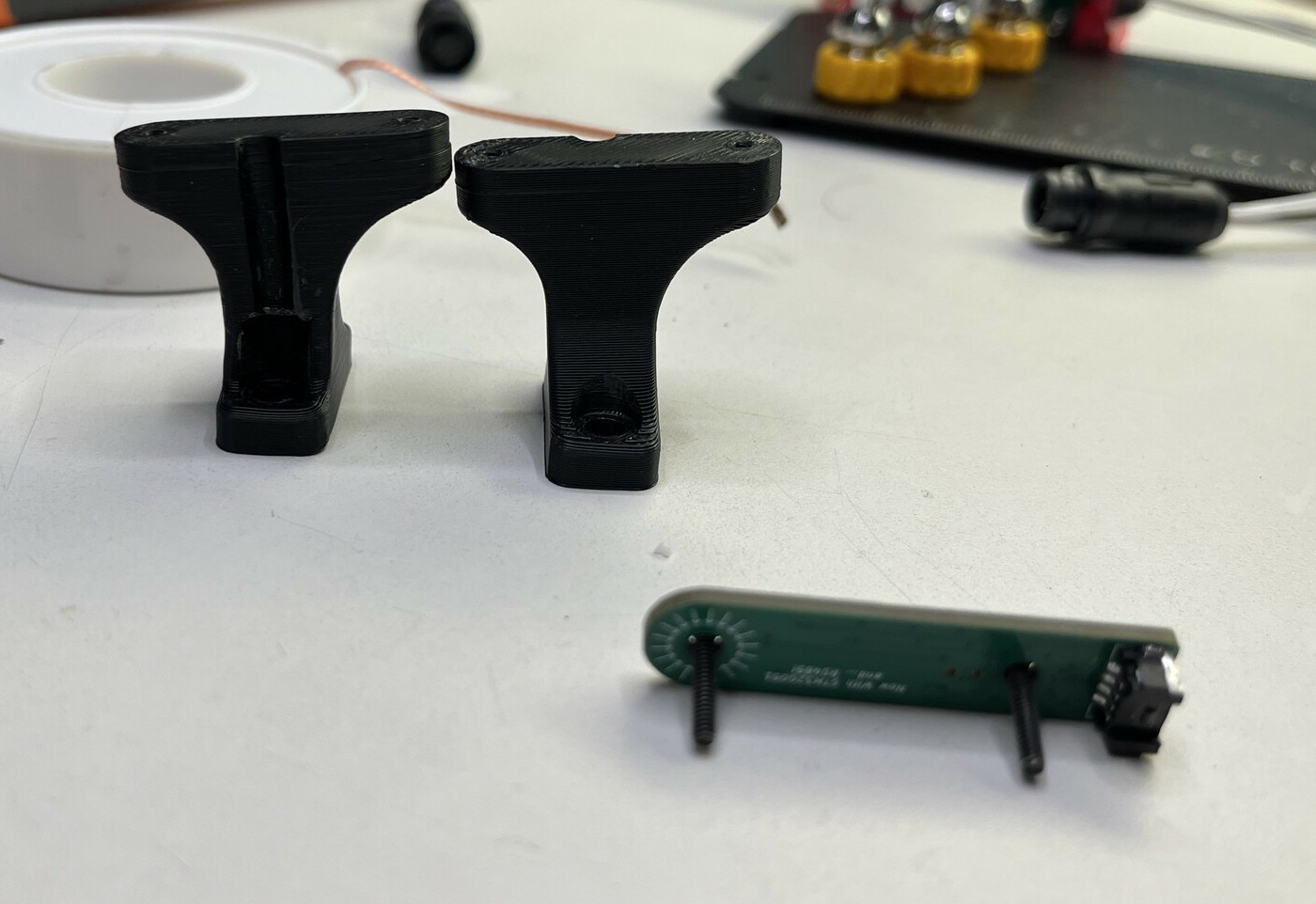
Wheelspeed mounts thanks to the mechanical team
Magnet Ring
The sensor board wasn’t the only improvement, I did finite element magnetostatic simulations of different magnet ring placements and geometries to optimize the resultant waveforms, and also to generate nonideal data and figure out how to compensate for it. The critical issue with the magnet rings that had been designed previously was the large amount of space betweeen magnets caused the radial magnetic field to contain higher order harmonics which made signal processing much more difficult (and compensating for it was relatively computationally expensive, slowing down overall processing)
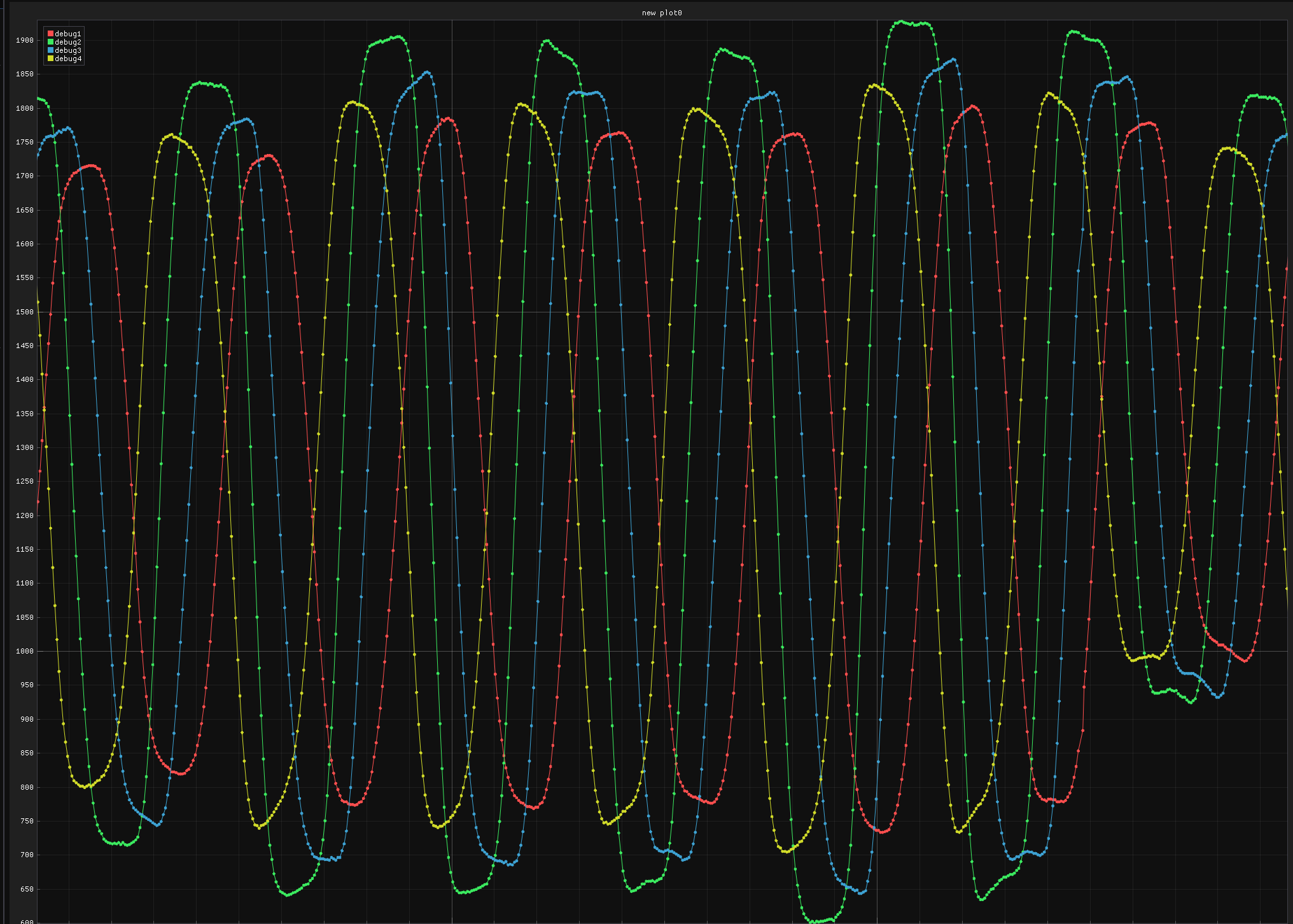
Raw digitized output from magnetometers before conditioning and processing (old magnet ring, not very sinusoidal!)
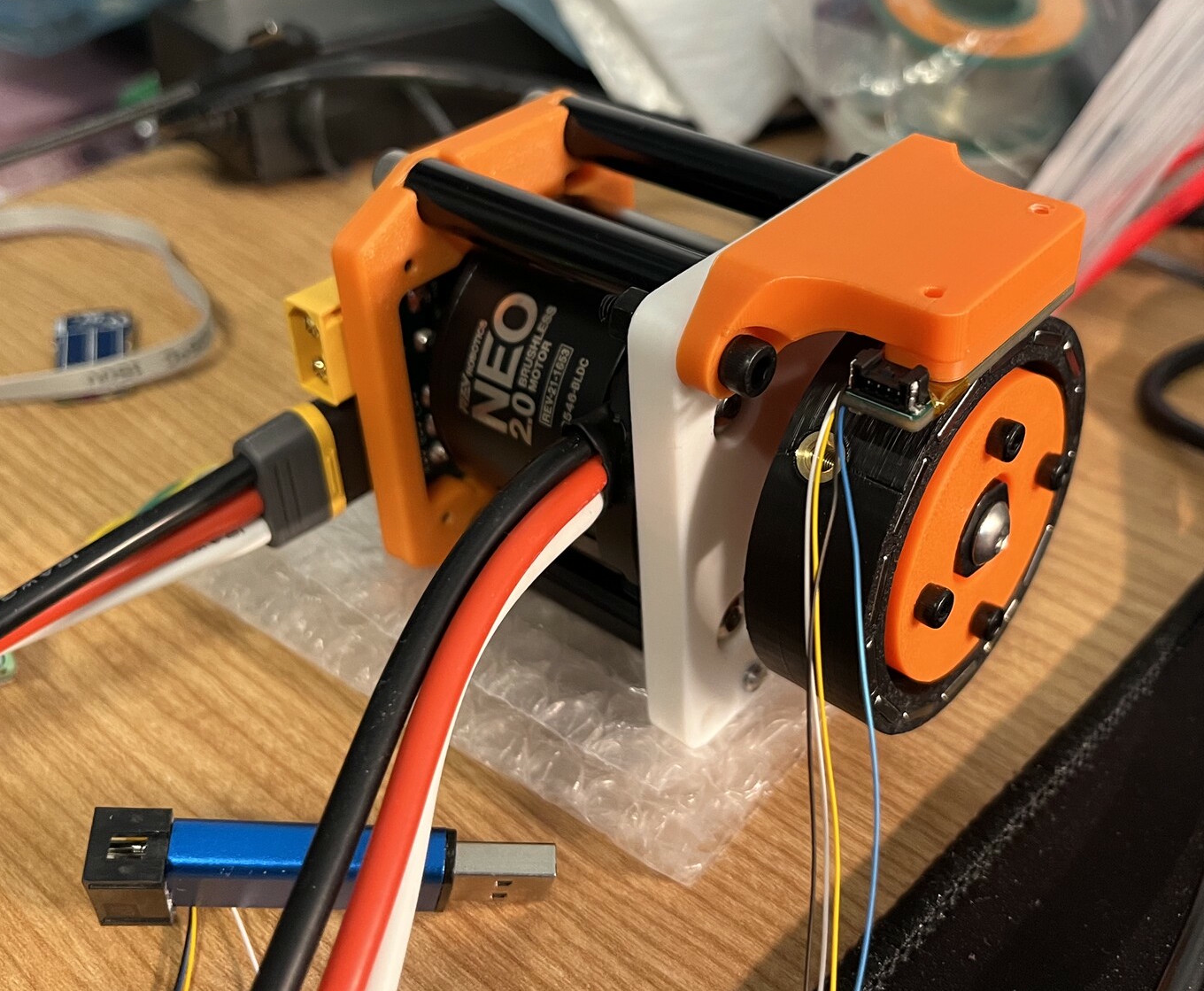
Full system test rig using my motor controller and a NEO 2.0 motor to spin the magnet ring
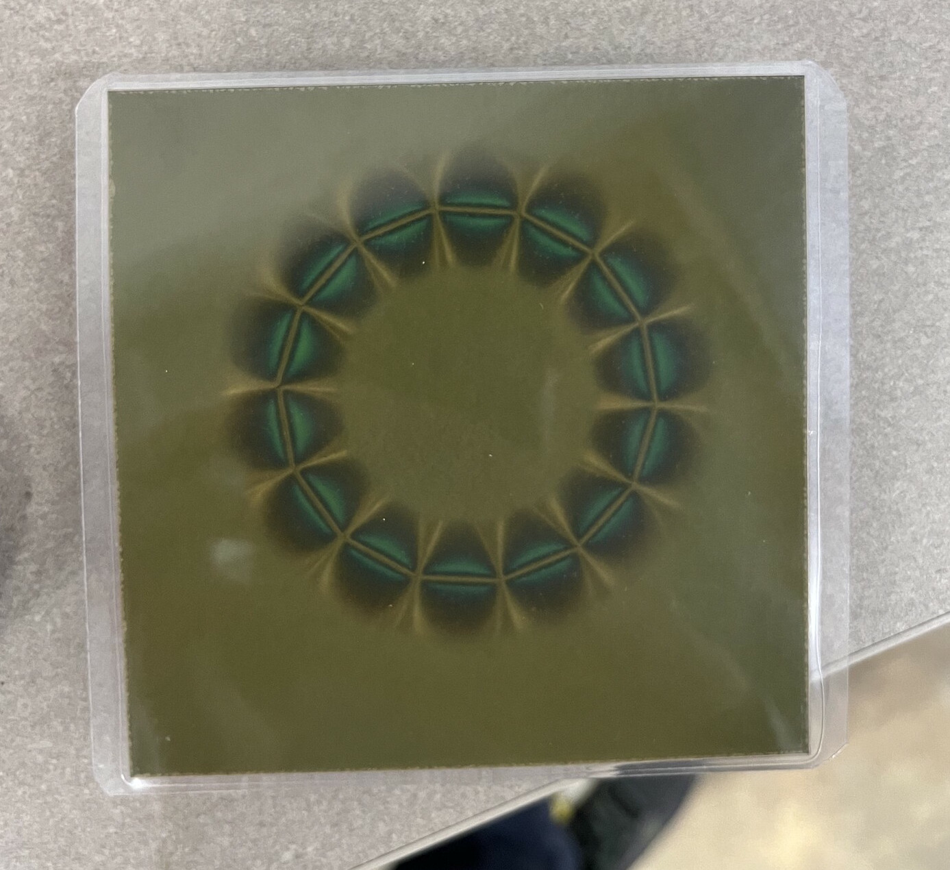
Magnet ring field (prototype for front wheels) through magnetic viewing paper
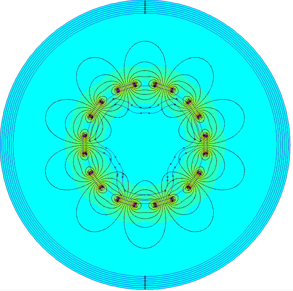
FEMM simulation of nonideal magnet ring with too few poles and large magnet-magnet spacing
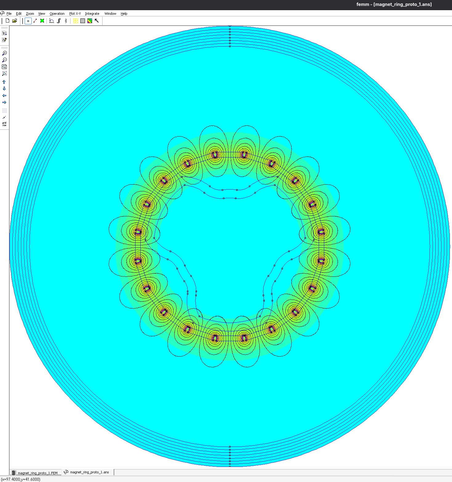
FEMM simulation of improved magnet ring with closer spacing and more sinusoidal field (below)
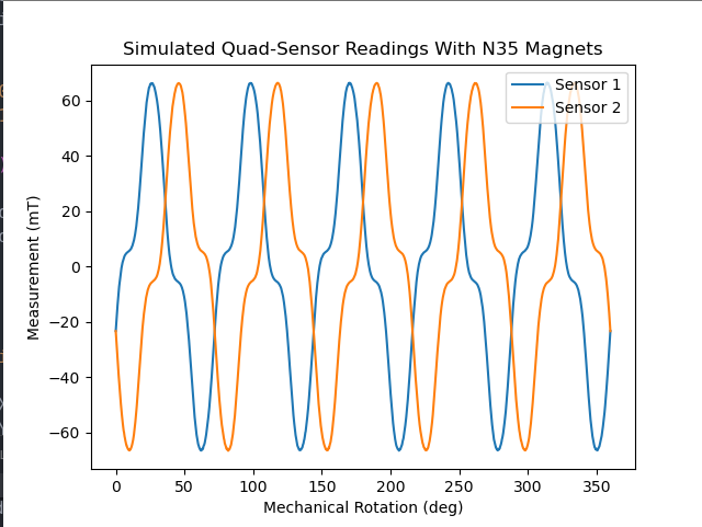
Hall sensor waveforms from nonideal magnet ring (from 2D simulation)
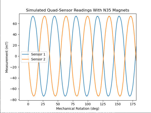
Hall sensor waveforms of properly designed magnet ring (from 2D simulation)
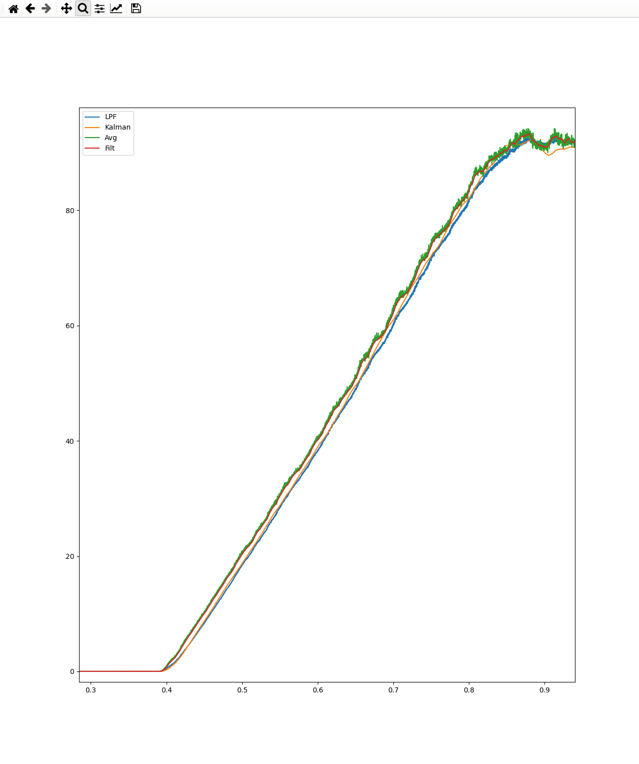
Testing various filter methods for velocity smoothing
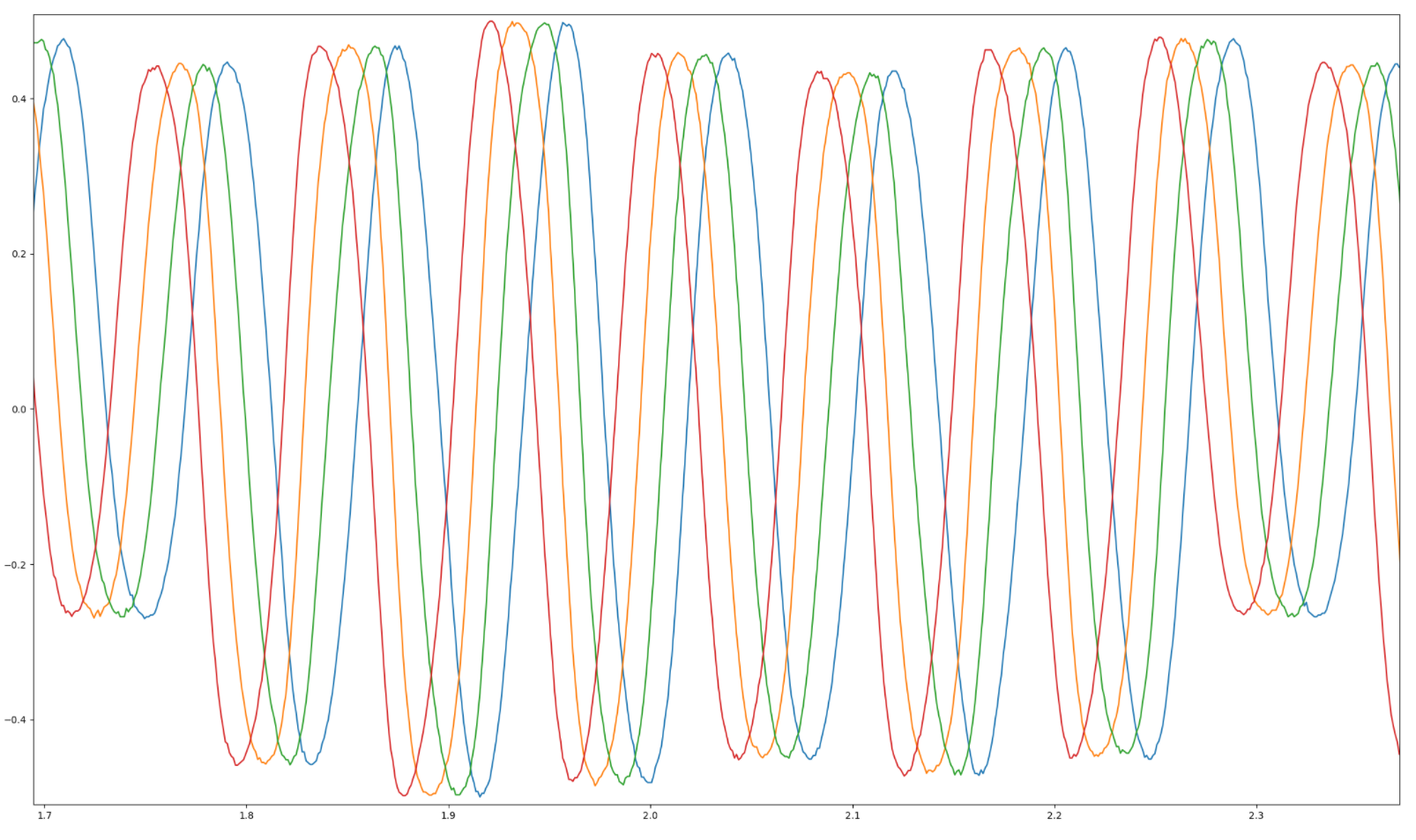
Real hall sensor waveforms from prototype magnet ring - amplitude variation (less of an issue) is visible due to the use of cheap magnets with wide ranging field strengths but the waveform shape is consistent
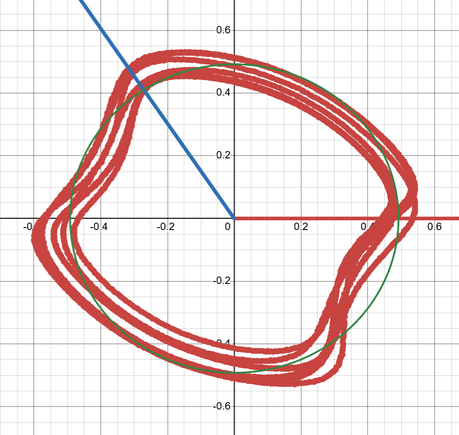
2D plot of raw data from two hall sensors (nonideal magnet ring)
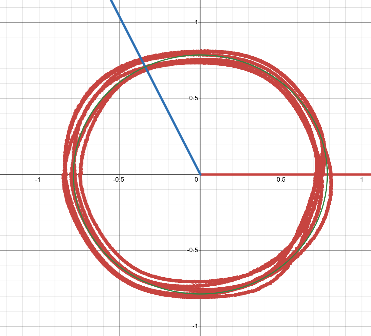
2D plot of hall sensor data after compensating for magnetic field “non-sinusoidalness”
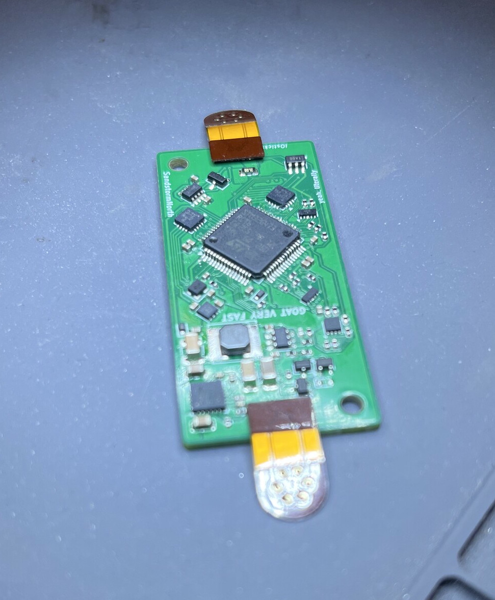
Partially assembled IO board used for wheelspeed signal processing (among other things) designed by SandstormNorth