Transverse Flux Motor
Falling down the rabbit hole of motor design and magnetics
A while ago while reading about motor topologies and thinking about the implications of the analysis in this amazing blog post, I came across transverse flux motors (TFMs). TFMs are an interesting motor topology that enables (at least partial) decoupling of the magnetic and electrical circuits in the motor assembly by (usually) wrapping a single coil around the inside of a multi-pole (sometimes called “flux modulating”) stator core to link (transverse) flux between adjacent poles of a rotor assembly through the (axial) stator coil. The paper “Transverse Flux Machine—A Review” gives a great overview of various stator and rotor structures and archetypes, but what I’m most interested in is the TFM’s ability to radically increase the pole count (and thus the torque constant) of a small motor without the need to wind a billion tiny stator teeth with their own coil. In theory, increasing the torque constant by adding more poles is one way to increase the motor constant (Km, Nm/sqrt(W)) of a motor to (hopefully) increase torque density. Honestly, I just was curious about how “good” of a motor I might be able to build using this design without any super fancy materials.
First Design Iteration
For my first shot at designing a TFM, I decided to pursue a flux-concentrating rotor design with thin magnets to get as fine of a pole pitch as possible. With some 0.5mm thick magnets and “faux-SMC” consisting of a mix of low viscosity casting resin and carbonyl iron powder I figured it might be possibly to fit 40 poles onto a 27mm diameter rotor. Unfortunately, after thinking about it for a long while, the manufacturing process for constructing just one of these rotors would be quite the undertaking (needing very fine 3D prints to hold magnets on the rotors, a three-piece modular jig to glue each phase’s ring of magnets onto the stator, constructing a mold & vacuum chamber for casting the magnetic resin, etc.). Unfortunately, too much tooling and setup for a one-off in my view. The stator of this motor I planned to get manufactured out of 0.76mm 1008 low-carbon steel sheet from SendCutSend - certainly not as good of an option as electrical steel laminations, but much cheaper. I was willing to accept that even at medium speeds the motor’s performance would probably be drastically reduced by eddy current losses, but at least I could probably get some good torque production at stall/low speeds with the reasonable magnetic permeability of 1008 steel.
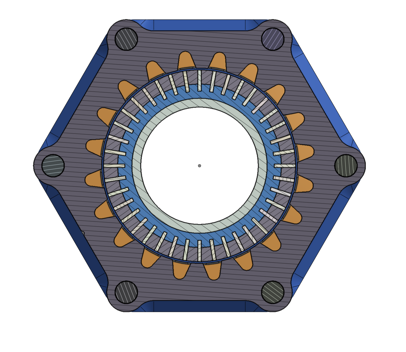
Axial section view
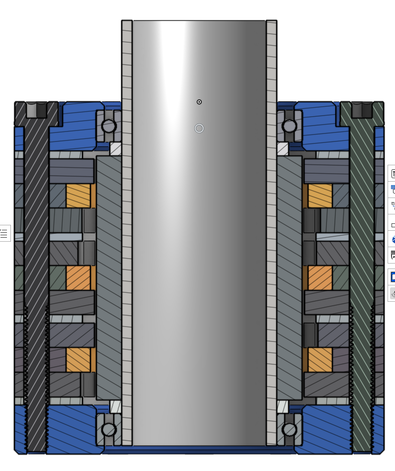
Side section view
Although I haven’t (and likely won’t) manufacture this design, I ran many 2D and 3D magnetostatic simulations and did a bunch of magnetic circuit calculations to estimate performance and motor characteristics. With some tweaks to the design (including a not-really-printable plastic magnet backing to prevent inter-magnet flux leakage) I was able to get the tooth flux density up to about 1T! With this pole count it looks like there would be ~130μWb of flux linked and a rough Km of 0.09Nm/sqrt(W) which isn’t bad at all for the size (~0.25kg). Unfortunately, the only way to get this good of torque density is to space the magnets closer together than I’d be able to 3D print the plastic backer for. With my next iteration I’m aiming to scale the design up a bit to not have to deal with 0.5mm thick magnets and be able to actually 3D print and machine parts at the scale I’ll need.
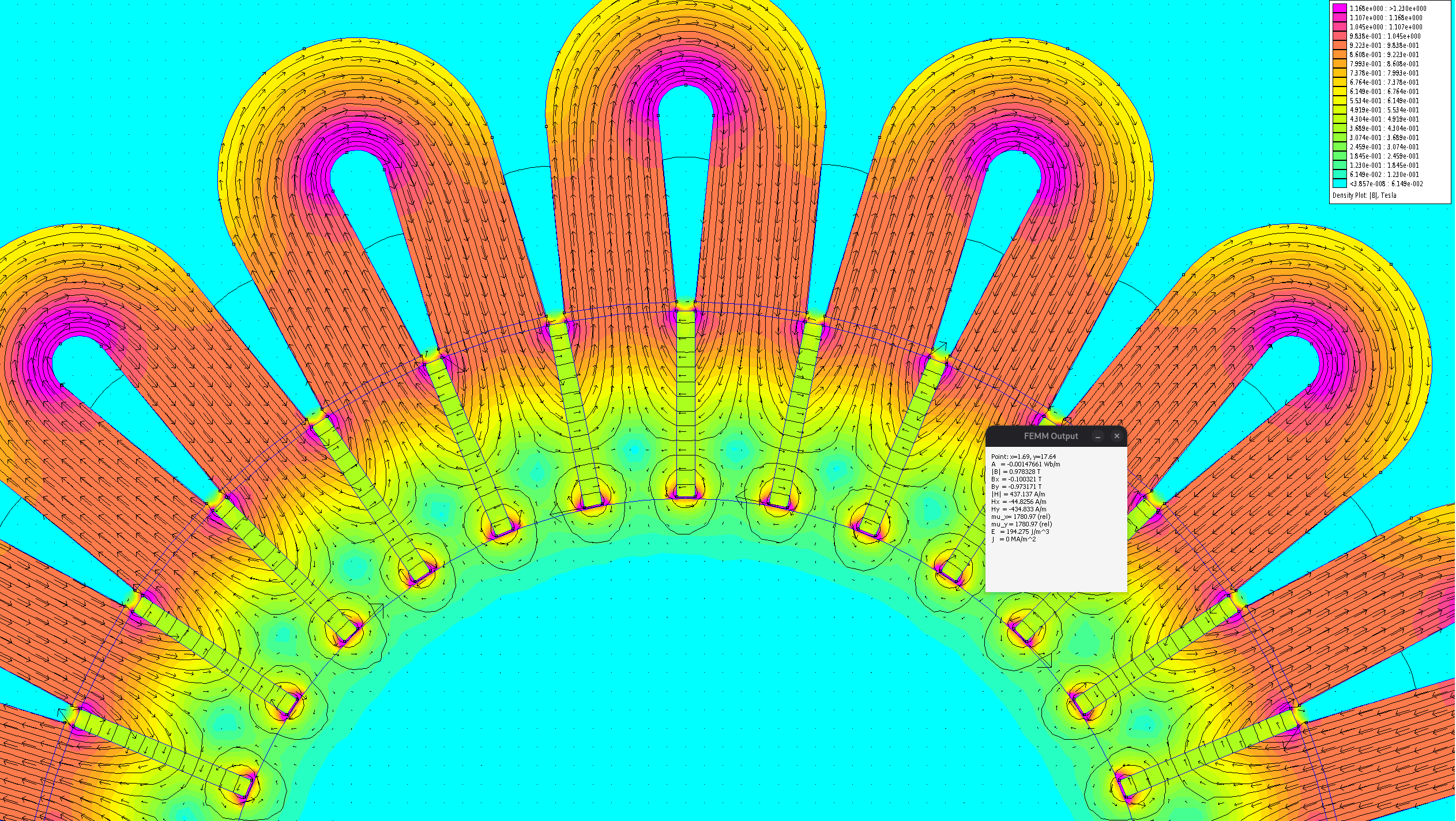
2D FEMM simulation of flux concentrating rotor with mock stator
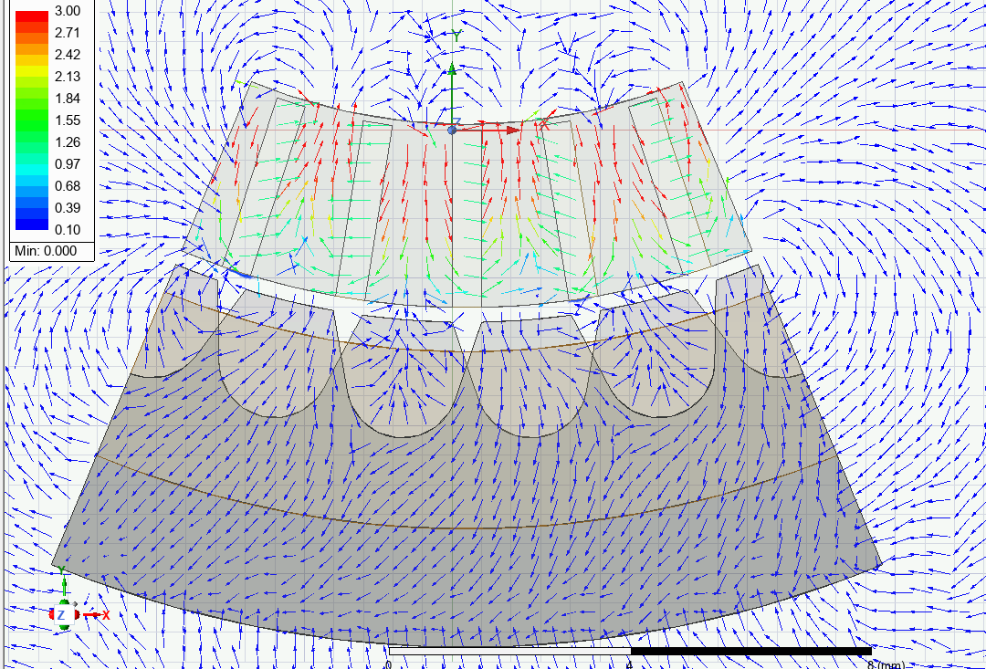
Ansys Maxwell simulation of flux before addition of anti-leakage plastic magnet backing
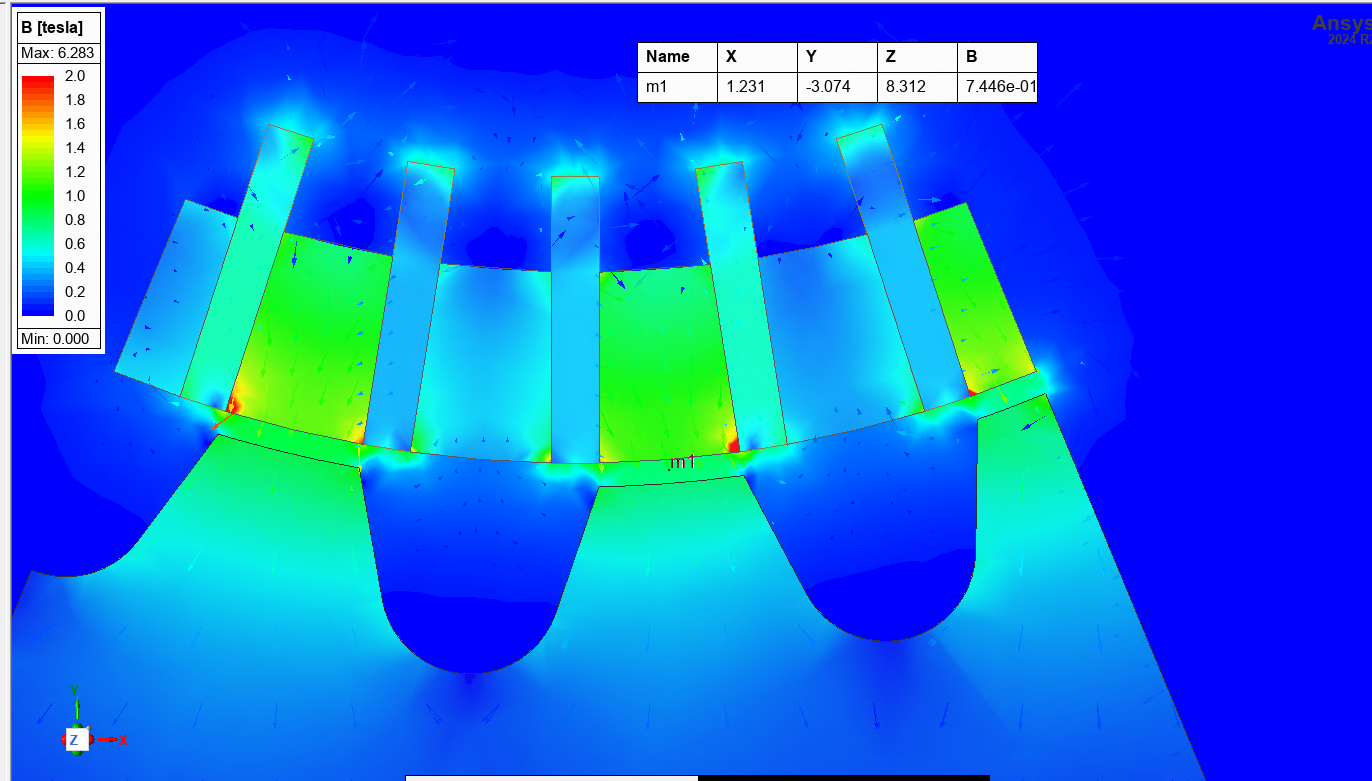
Simulation of flux after addition of anti-leakage plastic magnet backing (much increased tooth density)
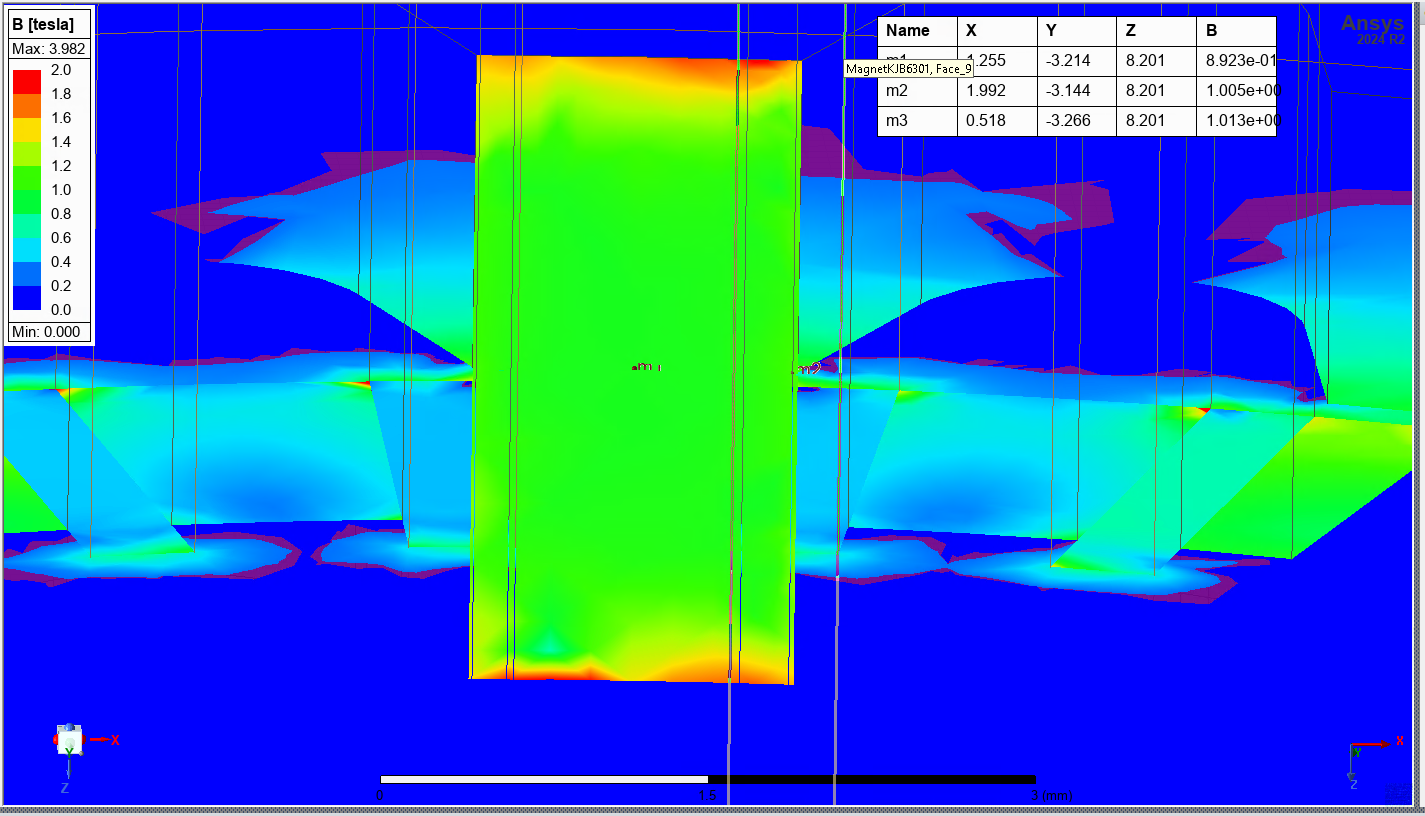
Flux distribution of a single tooth face
Current Status:
At this point I’m on my second design iteration aiming to improve manufacturability of the motor while still vying for respectable torque density. More updates coming soon!
Resources:
- Transverse Flux Machine—A Review
- OneWheel TFM Teardown
- Design of an In-Slot Cooled Air-Core Flux-Focusing Permanent Magnet Synchronous Machine for Electric Aircraft Applications
- Flux Linkage in Transverse Flux Machines with Flux Concentration
- Structural Dynamic Behaviour of a Linear Transverse Flux Machine
- US8395291B2: Transverse and/or commutated flux systems for electric bicycles
- Rim driven thruster having transverse flux motor
- Transverse Flux Motor - Penn State Altoona (Nicholas Kuhn)
- MDSM 2026: Reinventing the Motor: How Transverse Flux Technology is Transforming Industry
- Design aspects on a transversal flux machine with SMC stator